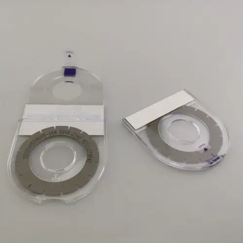
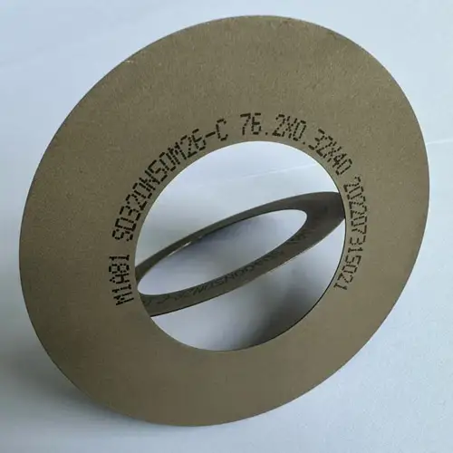
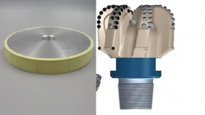
Wafer dicing blade is mainly composed of electroplated nickel bond and diamond particles, also known as hub dicing blade in the industry. When cutting, the spindle drives the dicing blade to rotate at high speed to obtain high rigidity, thereby removing material and achieving cutting. (Related articles:Explore The Spindle Speed Of Dicing Machine On Cutting Quality!)Because of the blade with thickness, a larger line width is required for cutting.
Metal Dicing Blade
Resin Diamond Blade
Electroplated Blade
The minimum cutting line width of diamond dicing blade can achieve 25-35μm. It needs to replace different dicing blade when cutting wafers with different materials and thickness. During the rotary dicing, deionized water can be used for cooling the blade and remove the silicon debris. Today, New Diamond Company writes a article about the knowledge of the diamond dicing blade for semiconductor integrated circuit.
Structural Characteristics Of Wafer Dicing Blade
The surface of the cutting blade is rough and sticky, with raised hard particles and cutting edges.Ordinary cutting tools have a smooth surface at the tip, sharp edges, and a large angle between the tip and the horizontal plane. The surface of the dicing saw blade tip of the wafer saw blade is rough, and the cutting edge is approximately rectangular, with an angle of nearly 0 ° with the horizontal plane.
Components Of Wafer Saw Blade
High Speed Rotation
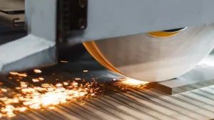
Ordinary cutting tools apply concentrated stress on the surface of the object with sharp tips, which can directly split the object for cutting. The wafer saw is different from ordinary cutting tools. Due to its inherent structure and material features, the dicing blade cannot achieve cutting during static or low-speed rotation, and must rotate at high speed to obtain high rigidity, thereby achieving cutting in the form of crushing and removing wafer material .
In this cutting method, the diamond dicing blade cuts the wafer groove at a high speed of 30000~40000 r/min. At the same time, the workbench carrying the wafer moves in a straight line along the tangent direction of the contact point between the dicing blade and the wafer at a certain speed, and the silicon debris left by cutting the wafer are washed away by deionized water.
Wafer Dicing Blade Edge
The wafer saw blade edge is formed at the cutting edge after sharpening, consisting of hard particles in the direction of the blade and fine grooves or voids at the end of the binder (see Figure 2-18), which vary depending on the blade formula. The wafer dicing blade edge can removal and cooling, and the blade edge maintains the cutting ability of the blade.
Diamond Dicing Balde Edge Movement Mechanism
Table 2-3 shows the material parameters of three types of dicing blades, including abrasive particle size, concentration, and bonding agent strength. Blow picture shows the scanning electron microscope (SEM) image of the nickel bond diamond dicing blade.(Related articles:How To Choose The Bond Type Of Dicing blade?)
Three Kinds Of Dicing Blade Material Parameters
Scanning Image Of Diamond Dicing Blade With Nickel-Based Binder
Cutting Mechanism Of Dicing Blade
Impact
When cutting hard and brittle materials such as silicon, the wafer dicing blade relies on high-speed rotation to cause high-frequency impact of hard particles such as diamond on the wafer, forming microcracks on the surface. After crushing, the debris is carried away by the blade edge.
Schematic Diagram Of The Cutting Mechanism of The Dicing Balde
Scraping Off
When cutting ductile metal materials, the blade edge continuously scrapes the surface of the object, roughening and removing debris.
The impact of hard particles and the scraping of the blade edge enable the material to peel off from the surface of the object, while the blade edge can promptly remove debris. These two jobs together to keep the surface material of the object continuously peeled off, achieving the cutting effect.
In order to remove as little material as possible, the thinner the dicing blade is , the better is. However, if the dicing blade is too thin, it is easy to deform during the cutting process, resulting in poor machining quality or even damage to the workpiece. The relationship between the protruding edge length of the blade and the thickness of the silicon wafer is shown in Table 2-4.
Blade Edge And Line Width
The line width of wafer saw refers to the width of the lines that need to be broken when using a dicing blade to cut the wafer. It is a characteristic dimension of the cutting process and represents the technical level of the cutting process. There are three main factors that affect line width:
Blade thickness.
Chipping size.
Expanding size.
Relationship Between Dicing Blade and Dicing Line Width
Above Picture shows the relationship between the dicing blade and the line width. The relationship between the line width and the main factors is as follows:
W=t blade+2W chipping +2W expansion
In the formula, W is the line width of the wafer saw. t blade is a ruler.W chipping refers to the chipping size. W Expand to the size of the burr expansion area.(Related articles:Hot to Solve Problem of Chipping in Wafer Saw!)
Blade Wear
Based on the cutting form of the blade (high-speed rotation, horizontal feed) and the working environment (deionized water and additives), the blade is mainly affected by the following effects:
Mechanical stress, normal and tangential pressure, and frictional force of chips.
Thermal stress, temperature rise and thermal stress caused by friction.
Chemical corrosion, pH value of cutting water and chemical reactions.
In general, continuous cutting of blades is mainly considered the wear caused by mechanical stress. The composition, structural features, motion mode, and working environment determine that the blade wear mainly consists of two modes: hard particle fracture and binder wear.
Fracture
Under long-term impact, some hard particles may rupture and wear, as shown in blow picture
Hard Particles Break Upon Impact
Abrasion
When cutting, the binder wrapped around the hard particles will also decrease due to wear. When the binder decreases to a certain extent and is no longer sufficient to withstand the force of the cutting object and chips, the hard particles will naturally fall off , exposing new particles and forming a new blade edge.
It can be said that the dicing saw blade is undergoing a process of regeneration while wearing out. The fracture of hard particles can form sharp angles on the fracture surface, allowing the blade to maintain its sharpness. The hard particles will naturally fall off, exposing new particles and forming a new blade edge. By maintaining appropriate wear through parameters between the wafer dicing blade and the object being cut, the blade can maintain a relatively stable chip force.
Wear of Binder Causes Hard Particles To Fall Off
The material, structure, wear condition, grain size, hardness, bonding agent, dressing condition of the surperabrasive wheel , as well as other factors such as workpiece material and cutting parameters will directly affect the grinding roughness of superabrasive wheel. In actual grinding process, it is necessary to comprehensively consider and control these factors in order to achieve ideal machining results and surface roughness of the workpiece.
Research has shown that the wear of dicing blade during the cutting process can be divided into two stages. The first stage is the transition phase, where the cutting distance ranges from 0 to 300m, and the width of the cutting seam, blade wear rate, and surface roughness rapidly increase.
The second stage is the stable phase, where the cutting distance is between 300-2000m, the blade wear rate slowly increases, and the width of the cutting seam and surface roughness slowly decrease. This is because during the transition stage, the particles with less bonding between diamond and blade first detach, leaving voids, increasing the surface roughness of the wafer dicing blade, and resulting in larger chip size. In the stable stage, most diamond particles are evenly embedded in the binder, resulting in uniform wear. Therefore, the roughness of the wafer dicing blades tends to stabilize.
The dicing mechanism of these two stages is different. In the transition stage, the impact and friction of diamond particles dominate the cutting in the stable stage, while the wafer is cut by diamond friction. Blow picture respectively show the relationship between the width of the cutting seam, blade wear rate, Dicing blade surface roughness, and cutting distance.
Relationship Between Cutting Seam Width and Cutting Distance
Relationship Between Blade Wear Rate And Cutting Distance
Relationship Between Blade Surface Roughness And Diamond Cutting Distance
Collection Of Diamond Dicing Blade
Blade For Cutting QFN Package
Blade For Cutting PCB
Blade For Cutting DFN Package
Blade For Cutting EMC Package
Blade for Cutting Metal Oxide Film Resistor
Blade for Cutting Optical Glass
Blade for Cutting Ceramic Substrates
Blade for Cutting LED Package
The above is the popular science knowledge of wafer dicing blade of semiconductor integrated circuit shared by the editor, including the wafer saw principle, characteristics, cutting mechanism, and causes of blade wear. If you have any questions about dicing, please leave us a message, and we can communicate more about resin, metal, hybrid bond diamond dicing blade.