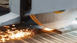
Dicing saw process also known as dicing saw machine cut the cutting area of wafers( or other hard and brittle materials) at a speed of 30000 to 60000 per minute with strong grinding as mechanism and an air static electric spindle as the executing element. At the same time, the worktable carrying the wafer moves in a straight line along the cutting line direction of the dicing blade and wafer contact point at a certain speed, splitting each chip with individual electrical components.
Main Process Requirements For The Operation Of The Dicing Saw Machine
With the development of electronic products, the market has put forward higher requirements for semiconductor packaging technology. The requirements for smaller, lighter, lower power consumption, and higher reliability are constantly changing, and emerging processes have made the cutting objects various, resulting in more complex cutting processes.

In order to improve dicing quality and processing efficiency, should analyze the factors that affect dicing quality. Now let’s make a systematic analysis of the key factors that affect the dicing quality during the dicing process.
Spindle Of The Dicing Saw Machine
The spindle of the dicing saw machine adopts an electric spindle supported by air static pressure. There are DC spindle and AC spindle.
DC spindle
① Adopt axial forced ventilation cooling or heat pipe cooling to improve the cooling effect.
② The constant torque range is below the basic speed, and the constant power range is above the basic speed.
③ Mainly using transistor pulse width modulation speed control system for speed regulation. Usually equipped with detection components for feedback.

Usually equipped with detection components for feedback.
AC spindle
① Specially designed squirrel cage three-phase asynchronous motor.

② Similar to DC spindle motors, the constant torque region is below the basic speed, and the constant power region is above the basic speed. When the speed exceeds a certain value, the power speed characteristic curve will tilt downward.
③ The vector control speed control method is widely used for speed control.
The structural differences cause higher speed control accuracy of DC spindle(through feedback compensation of speed). The vibration of the spindle is smaller during operation, and the dicing effect is better. But the torque is relatively small compared to the same power AC spindle, which results in insufficient cutting force for thicker and harder glass, ceramics. Its dicing field mainly targets silicon wafers, gallium arsenide, oxide wafers, etc. The AC spindle has a high torque and vibration, mainly for the processing of hard and low precision products such as LED substrates, raw ceramics, and new electronic packaging.
Cooling Water Source
There are spindle cooling water and cutting cooling water for dicing saw machine water sources.
Spindle Cooling Water
The spindle cooling water is to cool and protect the spindle. The deionized water should be used inside the spindle circulating, otherwise it will cause block. The temperature of the cooling water should be constant at room temperature.

It is recommended to set the constant temperature water tank, otherwise the dicing saw blade marks will be offset during the dicing process. The air spindle is a critical component that requires regular(6 months) inspection of the spindle water circuit to prevent scale from blocking the pipeline, otherwise it causes damage to the spindle motor.
Cooling Water Of Dicing Saw
The deionized water is mainly used. The special accessories can be added according to the product needs, such as adding carbon dioxide gas, changing water quality resistance value, etc.
Micro-porous Ceramic Suction Cup

Advantages: Uniform suction force, suitable for suction of products with thin and brittle attached film, no damage to the blade, reduced back chipping and good dicing effect.
Disadvantages: The surface needs to be fully covered, otherwise the suction force is insufficient. For smaller workpieces, the waste of blue film is severe, and the micopores are easily blocked, making it unsuitable for processing environment with high dust.
Diamond Dicing Blade
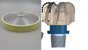
Dicing blade is mainly composed of diamond particles, bonding agent, etc. The bonding agent is used to fix diamond particles in the blade. Therefore, the performance of the dicing blade is mainly determined by the diamond particle size, diamond concentration and the type of bond.
There are hubless and hub dicing blade based on the type of the bonding agent. The hubless dicing blade usually adopt resin and metal bond, with good flexibility, and usually used for cutting hard and brittle materials such as quartz, glass, ceramics, tungsten carbide, LT, LN, AlN, etc. The hub dicing blade is usually electroplated, which make them high rigidity and wear resistance. It is suitable for cutting harder materials such silicon wafer, PCB, etc.
Hubless Dicing Blade
The hubless dicing blade is fixed with flanges, which features big blade exposure, can process thicker products, low price, cost-effective.
In order achieve the true circle effect, it need to pre cutting with dressing board, and there will be slight jumping at the contact part between the dicing blade and flange, resulting in poor dicing effect. Resin bond diamond hubless blade has good sharpness and good cut. Metal bond hubless blade has long life. Hybrid bond hubless dicing blade can cut soft materials and ensure the perpendicularity of the cutting surface, for BK7 and SF57 soft glass.

Hub Dicing Blade

The body of hub dicing blade is fixed on the flange by high temperature and high pressure, Generally, it is an electroplating bond dicing blade.and can be confirmed to be truly round before leaving factory. Due to the integration of blade and flange, it can process high-end products. However, the manufacturing method determines that the blade exposure cannot be too large, the blade exposure is from 0.30 to 1.15mm. This kind of dicing blade cannot process thicker products.
This kind of dicing blade cannot process thicker products.

Basic Principle For Selection Of Dicing Blade:
More softer blade material will be chosen when dicing the more harder materials. More harder blade materials will be chosen when dicing more softer materials. If choose superhard blade for hard and brittle materials, there will be back chipping during dicing. According to chipping requirements and material performance, choose the blade bond, concentration, diamond particle size.

The thickness of the dicing saw blade is first determined based on the width of cutting slot and the physical and chemical properties of the material. For some hard, brittle and chipping materials, need to choose the dicing blade based on the material properties and the chipping process requirements.
On the premise of meeting the customer’s dicing requirements, choose the dicing blade with large grit and thicker to improve cutting efficiency. The selection of diamond particle size of blade is determined by various factors such as the material of the product to be cut, chipping requirements, and cutting efficiency. Usually, for harder materials, we choose dicing blade with larger diamond particles to improve dicing ability. With sufficient dicing force, we choose the diamond grain size similar to the chipping size. For example, if the chipping requirement i less than 10μm, the diamond grain size of dicing blade is not over W10.

If the workpiece is thin, there will be back chipping after dicing. For example, if the dicing process parameters are the same, two kind of dicing blades with different diamond grain size are used for dicing. The left figure shows that diamond dicing blade (2000#) with diamond grain size of 4-6μm are used for processing, and the back chipping is more obvious. The right figure shows the diamond dicing blade(4800#) composed of ultrafine abrasive particles for processing. There is also a choice of diamond grain size of diamond dicing blade in the case of front chipping. Choosing the appropriate chipping reduces the impact force on the workpiece. The above need to be considered comprehensively.
3. Operation Process And Notes Of Dicing Machine
3.1 Operation Process
Before using the wafer dicing machine, prepare the wafers to ensure they are clean, flat, and accurate. Next, you can use the wafer dicing machine by following these steps.
3.1.1. Preparation:
① Check wafer quality: Check for cracks, dirt, and etc. on the wafer to ensure that it does not affect chip quality when dicing.
② Prepare and install blades, and then clamp the blades.
3.1.2. Adjusting Parameters:
Adjust parameters based on the material, size, and required chip size of the wafer, including dicing speed, depth,dicing path, etc.
3.1.3. Dicing Saw Operation:
① Positioning the wafer: Place the wafer on the dicing machine workbench and position it to ensure the accuracy of the dicing blade.
② Start the dicing machine: Start the dicing machine and start the dicing operation according to the preset parameters.

3.2Notes When Dicing
3.2.1. Avoid wafer displacement and collision:
Ensure that the wafer runs smoothly during the dicing process, avoiding wafer displacement and collision, which may damage the quality of the chip. The most common problem is chipping, which includes front chipping, back chipping, corner loss and cracks. There are many different factors that can cause chipping such as the surface condition of the workpiece, the condition of the adhesive film, cooling water, blade, etc.
3.2.2. Clean the cutting area:
There will be chips during the dicing process. Regularly clean the cutting area to prevent chips from affecting the cutting quality.

3.2.3. Operation after dicing:
① Check the quality of the dicing blade: After the cutting is completed, check the quality of the chip including size, surface defects, etc.
② Cleaning the chip: If the chip is dirty, clean the chip with the suitable cleaning solution.
③ Storage chip: When storing chips, care should be taken to avoid contamination or damage.
3.3 Maintenance of Wafer Dicing Saw Machine
3.3.1. Daily maintenance
In order to ensure that the wafer dicing machine maintains optimal performance , we need to carry out daily maintenance. These tasks include regularly cleaning equipment casings, cutting tools, cutting fluids, and workbenches, as well as inspecting equipment for wear, oil leaks, or cracks. In addition, clean and maintain the equipment so that it can return to its optimal state before the next use.


3.3.2. Prevention and elimination of potential problems
During the use of wafer dicing machine, there are some potential problems that may affect the performance and efficiency of the equipment. To prevent and solve these problems, we need to pay attention to the following points:
① Use the correct cutting tools and equipment settings, and configure appropriate cutting parameters.
② Control the temperature and concentration of cutting fluid to ensure cutting quality and efficiency.

③ Regularly inspect various parts of the equipment, such as dicing blades, motors, transmission systems, and lubrication systems, to avoid malfunctions or accidental damage.
④ If any problems are found with the equipment, repair or replace parts timely to avoid safety risks and economic losses.
In summary, wafer dicing machine is key equipment for achieving mass production and improving production efficiency. When using a wafer dicing machine, need do some preparation work and adjust the parameters, and operate the dicing machine according to the operating procedures to ensure the stable operation and extend the service life of dicing machine.
Actual Cases
The stable balance is achieved with the dicing blade by continuously modifying dicing parameters and process settings to effectively solve the problems of chipping. The following is detailed explanation of the dicing parameters and process settings.
- ID naming: D represents DFN product; 0303 represents the product size; 050 represents the pin spacing; 010 represents the number of pins; 1 represents how many units the product has; 32 represents the thickness of the dicing blade.
- Spindle speed: ranging from 10000 to 30000rp/min, commonly used value is 23000rpm/min.
3.Dicing mode: SUB-INDEX indicates cutting according to the dicing mode set.
- Blade height: Fully automatic range of 0.4~0.6mm, commonly used value of 0.5mm.
- Feed speed:
Pin spacing of 0.3-0.35mm, and feed speed of 45mm/s.
Pin spacing of 0.4-0.45mm, and feed speed of 55mm/s.
Pin spacing is 0.5mm, and feed speed is 60mm/s.
- Z-axis automatic descent: The dicing blade wears out during the cutting process, and the Z1/Z2 automatically descends after reaching the set length.
- Automatic height measurement: When the dicing distance of Z1/Z2 reaches the set value during/after cutting, automatic height measurement is available. Z1/Z2 can be measured simultaneously, and Z1/Z2 can be measured simultaneously or separately. (Simultaneously with Z1: indicates that when the cutting distance of Z1 axis reaches the set value, Z1 and Z2 will measure the height simultaneously. Not at the same time: means that when either axis reaches the set value, both axes measure height simultaneously

- Least squares method – most accurate parameters: the amplitude and number of steps of the X-axis on each surface during the alignment process. The parameters control the cutting at the center point by setting the least squares method.
- Adjustment range value: deviation value during calibration, equipment alarm for any point exceeding the range, 1B range value ≤ 0.025, commonly used value 0.022; The range value of 4B is ≤ 0.025, and the commonly used value is 0.018.
- 1 represents CH1 surface, 2 represents CH2 surface, 3 represents CH1 surface flushing, and 4 represents CH2 surface flushing.
- The √ in the*represents the simultaneous double dicing of two steps. * 2: 1 represents Z1 axis, 2 represents Z2 axis, 0 represents control

Note
- Separate the CH1 and CH2 surfaces of the product (ensuring vacuum level).
- Edge removal is performed simultaneously with twoblades, following the normal cutting sequence. After edge removal, rinse with water to ensure that the waste edges are washed away.
- Cut the remaining products in order after the waste edge is removed.
- Ensure that the entire dicing process is not missed.
- The product needs to first remove all waste edges .
- After cutting the waste edge, flushing operation is required.

Align with special parameters:
- X/Y Step: The alignment step movement of each cutting in the X/Y direction.
The amplitude of the X-axis during θ adjustment: the movement amplitude of the X-axis during θ adjustment in the automatic alignment action of each cutting upwards.
Calculation method:
Ch1: (Ch1 product size+cutting width) × (Ch1 product quantity -1)
Ch2: (Ch2 product size+cutting width) × (Ch2 product quantity -1)
Notes:
- When the product size is very small, the X/Y step can be set to the size of a single product plus the width of the cutting track in millimeters to avoid missing the target during alignment and inability to pass through.
- 4B requires the addition of a waste edge distance (the width of the waste edge can be measured using a high-powered mirror or directly on the device).
For dicing saw process, it is theoretically simple, but it is a complex process with different cutting objects and requirements in the practical operation. In addition to matching the dicing blades, the parameter adjustment of wafer dicing machine is also highly required. It needs to be adjusted based on theoretical and practical dicing experience to ensure the dicing quality of the wafer.